Category: Mustang II Installed Pics

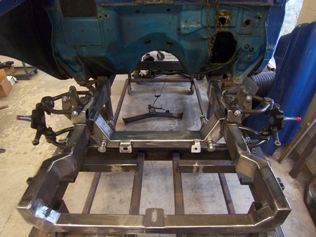
Photo Sharing: Mustang II in Vega wagon

Dear Welder Series…
I’ve finally put a representation of pictures together of my project and your product. It has definitely made this easier. This Vega wagon is ultimately getting a wide-body treatment as I chose the 58″ track M-II front to work with the C4 Vette rear at 59″ and wheelbase increased +4in. It will be a driver, not a show piece, for corner carving fun. My plan was/is to rough in the perimeter frame, weld body to it in various places and get it in rolling chassis. I’m almost there. The frame curves I’ve purchased from you has made this a lot easier and less expensive than mandrel bent. I’ve enclosed pics from rear frame section to the front crossmember. Everything will be blasted afterward and I can finish welding making it uni-frame per say and find the other body work needed. My small garage is only heated as needed during winter time so I thought I would keep as much metal covered as possible till ready to do body work. Pardon the hen scratching and tape. I did a lot of figuring and notes on the body as I did this. This Vega is only my 2nd complete car project. Been a fun learning curve for me using your pieces. My first project car is the 383ci V8-Corvair you see in background of one of the photos. I have a lot of photos documenting my progress but also as reference. They are not in any kind of order. Hope these pics show your product(s) in the best possible way, as they are a great product to work with. Thank you

Mike W
Orrington, ME


Dear Welder Series… 1936 Plymouth Mustang II?

Dear Welder Series…

I have included a couple pics so you can see what we have. The crossmember installed will be removed to install your unit. A gentleman started it with his own design and gave up so I appreciate your help on this. The white line is our wheel base of 113″ and that is your Z correct? I will get what you need from that.
Thank you so much.
Jeff

Dear Jeff…
Jeff, the stock wheelbase dimension will usually give the “Z” location. Sometimes the look is better when the wheel/tire is ahead or back slightly from the stock location. This is because of the vehicle rake or even the stock “look” of the wheel and tire in the fender opening that changes with the new ride height. If you have the luxury of putting a fender in place and mocking the tire, it could give  some relief to know the line you have was right all along. Or …

Thanks for the pictures.
I’ll try to get cut line info back to you quickly so you can get on with the build.
Paul

Dear Welder Series…

Hi Paul
We removed the engine and the other cross member to get more accurate measurements for your work sheets. I sent a pic of front frame also. Let me know if you need anything else and thank you for all your help.
Take care
Jeff

Dear Jeff…Jeff, this series of Plymouths gave us issues back in the 80’s when we had the first one to do. I think we were involved with another builder since then. He made new frame rails from the firewall forward.

The high frame arch makes it very difficult to install an independent front end.
The frame width is where the upper a-arm cross shafts will be and the frame arch is also there.
The work-around is to add to the bottom of the frame and remove from the top.
I can do some basic drawings that will show the height of the new bottom and top of the frame using the dropped spindles that you have I can do similar drawings for stock MII spindles.
Would you also please confirm the dimensions from ground to top of frame at CR and TR?
I’ll watch for your reply.
Paul

Dear Welder Series…

Hi Paul
Let me know when your free for a call again please. The plan is to install 2×4 at 13 1/8″ high and the same width as the inside of the existing rails and it should be more than 14 in in length of clean flat surface to work with on the top. I just want to talk before I cut it up.
Thanks
Jeff
Dear Jeff…
My drawings are all based on dropped spindles and 13” ground to the bottom of the 2×4.
Dear Welder Series…
Hi Paul
I have attached some pics of the Plymouth for you to have a look at. I got at it this week and it really went well and I thank you so much for all your help and engineering. I left the inner upper rails in as fillers for when the fenders are installed. We have some more finish work to do but we are really happy with the results.
Take care
Jeff
1953 Studebaker Pickup with a Welder Series Mustang II Crossmember

Dear Welder Series… 1953 International PU Mustang II

Dear Welder Series…
I want to purchase a coil spring front cross member kit. It is going into a 53 International with a stock tread width of 60-1/2″. Questions …. I have Granada rotors on MII spindles … do I need the 58″ or 60″ x-member? The frame width is 28-1/4″ out to out  …. which size will work best?I have seen the Swartz build, but can find no reference to which width he used.

Dear Rich…
Rich, I’m checking with Grant Schwartz now.
To decide the track width kit to use, position the wheels and tires that you’ll use in the fender opening and measure wheel mounting surface to surface.
28-1/4” outside dimension might require a work-around, but let’s take one step at a time.
Thanks for looking at Welder Series’ parts. Paul Horton

Dear Welder Series…
Here are the measurements for the frame. The outside measurement is 28-1/4″ from 6″ ahead of Z to 1″ behind Z then tapers to 28-7/8″ at 6″ behind Z.

Dear Rich…
Installation tips and cut lines drawings are attached.
Paul

Dear Welder Series…
I will take pictures as I go and will send you a file when the frame is done…. might be a month or so at the rate this old fart works….. and have to keep the house projects going to keep the boss happy. A Jag rear is the next stage of the project.
This project is replacing my daily driver as it has seen 12 years and a lot of abuse.  Engine is 5 cylinder M/B turbo and is still going strong. 

Dear Welder Series: 1929 Essex Mustang II Install

Welder Series offers a service where we can guide you where to cut the crossmember after you provide some key dimensions. Here’s how it works…

Mustang II Crossmember Trim Lines Worksheet

Dear Welder Series…

Hi Paul. Prior to me cutting the notches in my clip, could you have a quick look and see if it will work. I think this ok but….. Its on a 29 Essex no fender, with 2″ drop spindles. Frame width is 24″ inside and 28″ out side, Frame is 2″ wide and 2-3/4 ” high

Thanks John

Dear John… Good morning, John.

I’m working on your Mustang II cut lines and realized I didn’t ask some questions yesterday:

Are the frame rails parallel?  (28” & 24” from 5” ahead to 5” back from centerline)  If not, what are the dimensions at those points?

You said the rails are 2-3/4” high at axle centerline.  What is the frame rail height 5” ahead and 5” back from c/l?

Thanks.

Paul

Dear Welder Series…

Hi Paul
The frame rails are parallel. The frame rail height 5″ ahead is c/l is 2-3/4″ and 5″ back of c/l is 3-1/8″.
When fitting the cross member last night I had to grind a little more get it to fit . In my picture to you I had the depth of the cut at 2.5″, when it is now 2-3/4 ”

Thanks so much for your help !!!!

Cheers John

Dear John…

Hi, John.

Here are the cut lines to put the bottom of your frame 10-1/2” from the ground with dropped spindles and a 26” diameter tire.

Please send pictures when you get the kit installed.
Thanks for using Welder Series’ parts.
Paul Horton

Dear Welder Series…

Hi Paul
Please see attached pictures of the 1929 Three Window Essex Coupe 🙂
Thanks for all your help !!! Soon to be chopped and channeled.
Kind regards John

1956 International Pickup Mustang II

Grant Schwartz stopped in the other day to pick up a Mustang II crossmember, and I think he had it installed quicker than my kids can go through a jar of Elmira maple syrup.

Here are some pictures he took. To see more of Grant’s work, please visit and follow his Facebook page: https://www.facebook.com/schwartz.inc

Parts Used:


1934 Plymouth Mustang II Installed

I recently made the front clip for my project (1934 Plymouth 2 door sedan). It was a pleasure using your Mustang II crossmember kit! My job was easy because the rails are level, square and plumb but the directions were a great help and easy to follow. Thanks for a great product!

Jeff

You can also see how Jeff made a mock-up coil over using a tube with two tubes welded on the ends. This is always a good thing to have around to keep your car at ride height during the build. Remember, you use the coil over spring to support the car at the designed ride height.

Do you have some Welder Series parts on your car? Please consider sharing them; it’s always helpful to see other people’s work.

Thanks for using our parts, Jeff. Enjoy your Plymouth!

DW

Mustang II Installed Pics: 1952 Chevy Pickup

As Steve was installing his Welder Series coil over Mustang II crossmember, he snapped some pictures (do you still snap pictures with a digital camera?) and sent them to be added to our monthly photo sharing draw. I know he’s bought a triangulated four link for the same truck… I can’t wait to see those install pictures too! That’s great, thanks very much for using our parts, Steve.

Depending on your ride height, notching the top part of your frame rails might be necessary. The instruction sheets included in the kit will show you how to determine whether you’ll have to trim your frame or not.

Steve used a Mustang II 56″ track width for his ’52.

Send your installed pics to pictures@welderseries.com. We’ll enter you in a monthly draw to win a $50 credit on your account here.

1953 International Mustang II

What do you mean, “modify the rails”?

We have had quite a few questions about installing our Mustang II kit in cars that don’t lend themselves well to a conversion. Sometimes “modifying the frame rails” is necessary. What exactly do we mean by that?

I thought I’d put together some pictures that show a few frames that have been modified to accept a Mustang II crossmember. If you have any questions about your frame or any of our parts, please email or call toll-free: 1-888-648-2150.

This Oldsmobile frame has been bottlenecked to accept our Mustang II crossmember.

The '57 Oldsmobile has received a similar treatment, but the builder used larger diameter tubing straight forward from the firewall.
The ’57 Oldsmobile has received a similar treatment, but the builder used larger diameter tubing straight forward from the firewall.

You can see the spring clearance notch in the frame rail in this picture of the finished '57 Olds.
You can see the spring clearance notch in the frame rail in this picture of the finished ’57 Olds.

Here is a Welder Series Mustang II in a 1978 Volvo. Extra material was 'wrapped' around the existing front rails of the unibody car.
Here is a Welder Series Mustang II in a 1978 Volvo. Extra material was ‘wrapped’ around the existing front rails of the unibody car.

A '57 Ford frame has the springs mounted inside the frame rails.
A ’57 Ford frame has the springs mounted inside the frame rails.

The '57 has been cleaned up and 2x4 tubing was used to mount our MII.
The ’57 has been cleaned up and 2×4 tubing was used to mount our MII.

1953 International Mustang II

1953 International Mustang II

1940 Dodge Mustang II

1940 Dodge Mustang II

1940 Dodge Mustang II

1940 Dodge Mustang II

If you’ve put our in something “weird”, please send us some pictures!