Tag: custom

Dear Welder Series… Corvette sway bar questions

Dear Welder Series…

I am wanting to install a rear sway bar on my 1978 corvette. Due to modifications to corvette and rim/tire size, a factory bar will not work.
This kit seems to be the closest to what will work for me but it I am hoping to get some more information from you before I purchase.
1)  Can you confirm the length of the torsion bar is 45″? If not what is the actual total length. The corvette frame is right around 43-44″ wide  and it needs to sit directly under it. There is minimal area to go narrower but is probably possible. Obviously I can trim it too.
2)  The outer tube what is the supplied length?  — so I can figure out if an under frame mount will work or I will have to fab up some custom brackets.
3)  What does the under frame mount look like?
4)  The lower link mounts won’t work in my situation so can they be removed with the  coil over mounts for a bit more cost savings.
5)  Do you have a detailed drawing (or a scale PDF) that I could print out, cut out to see if it would work around the interferences I have.
If you had a 45″ kit without any bracketry (swaybar , tube, bushings, arms, couplers and rod ends for the links)  that would be ideal.
Thanks,
Mike

Dear Mike…
Hi, Mike.

1)  The actual sway bar is 45” long. One end has 1” of spline. This bar is designed to be used as-is or cut to length. We also have 45” bars splined both ends. The 3/8” thick arms mount outside the bar, so if the 45” bar was used as is, the distance outside the arms would be 45-3/4”.
2)  The supplied outer tube is 1-3/8” OD and 43” long.
3)  The under frame mounting bracket:
4)  The lower axle mounts for the links can be taken out of the kit:
5)  I don’t have a single drawing of the whole kit. Dimensions for the various parts should all be on the website.
Welder Series is a “builder supply” company and, as such, all parts are available individually. They are shown on our website with dimension details. Please get in touch again if we can give you some other info.
Thanks for looking at our parts for your project.
Paul Horton
Dear Welder Series…

Paul,
Thanks for the info, it helps greatly.
I am just working out  how to best mount it, what parts will work in my case and also ways to keep the weight of the added system in check.
Mike

Dear Welder Series… MII for Datsun 521?

Dear Welder Series…
Hello, I was looking at your Mustang II crossmember kit. I’d like to get one for my Datsun 521. I was wondering if you would be able to decrease the width of the crossmember sections by 3” to accommodate the more narrow track width of my truck. I guess I could section it myself but that wouldn’t look as clean. The suspension parts aren’t readily available for my truck so I’d like to use this setup.
Thanks,
John

Dear John…
Hi, John.

We can make special width crossmembers, but…
The actual track width might not turn out to be what you hoped for. The brake kit used can move the wheel in or out from where the stock Mustang II was. You might also find that narrow control arms can be used that will reduce the track width and give more clearance in the engine room for exhaust and steering, even if you will use the stock engine.
Our website has some Mustang II dimensions at http://welderseries.com/tech/tech-sharing/ifs-make-your-own/. These dims will give a track width of 56-1/2” when stock 1974-78 Mustang II rotors and control arms are used. Narrowing the dimensions, top and bottom, will bring the wheels closer together by that amount. Shorter control arms will do the same. The brakes used might move the wheels in or out. We have info about our brake kits at:
If you use 4-bolt MII rotors, there should be no change.
My suggestion is:
Get everything you need except the crossmember kit, springs, shocks, and the steering rack. (Wheels & tires, brakes, spindles, and control arms)  A custom rack will have to be ordered after the width has been determined. Springs and shocks can come after that.
Remove the stock front suspension.
Block the truck at ride height.
Mock up the wheels & tires, rotors, spindles and lower control arms.
Position the tires in the fender. The tires should be very close the vertical.
Block the lower control arms at horizontal.
Measure the lower control arm mounting hole center-to-center.
Subtract that dimension from 22-1/4”. This is the amount to remove from the crossmember.
Buy our 56-1/2” kit and remove that amount from between the rack mounts.
The rack will have to be shortened the same amount.
Before doing much more, check the cost of this to be sure you are comfortable with it.
I hope this helps with this part of the project.
Paul Horton
Dear Welder Series…
Paul,

Thank you for all the information and help. I figured that the control arms would have to be shortened as well. I saw a couple of your customers vehicles who did the same thing. Have a Happy New Year.
Johnathon

Custom Axle Brackets

We’ve always designed our brackets for 3″ axle tubes, but once in a while someone asks whether we can make them for other sizes. Here’s the process:

This can be done for any axle housing diameter, bushing width, or bar location relative to axle centerline.

We charged C$29/ea for the brackets, plus labour to weld them. Turnaround was a few days. Please get in touch if you have a special project that you think we can help with.

Custom Work: Amp Stand

Welder Series does special parts for many things beyond hot rods. One personal project done for me, Paul Horton, is the tilt stand for the ZT Amplifiers that I use in my “second” career. In small club settings, I use the ZT Acoustic Lunchbox tilted back 30 degrees to project my voice, guitar, and drum synthesizer. A second ZT Lunchbox is used as a monitor for the drum machine. The stand lets it be tilted back at 60 degrees as a monitor. You can check out the Facebook page to see a short video.

Custom work is an almost daily part of Welder Series. If you would like a quote for your own idea, please email paul@welderseries.com.

1953 International Mustang II

What do you mean, “modify the rails”?

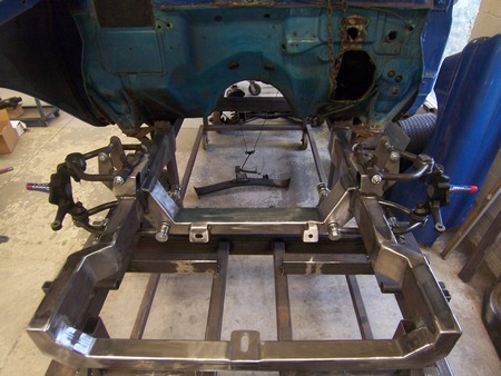
We have had quite a few questions about installing our Mustang II kit in cars that don’t lend themselves well to a conversion. Sometimes “modifying the frame rails” is necessary. What exactly do we mean by that?

I thought I’d put together some pictures that show a few frames that have been modified to accept a Mustang II crossmember. If you have any questions about your frame or any of our parts, please email or call toll-free: 1-888-648-2150.

This Oldsmobile frame has been bottlenecked to accept our Mustang II crossmember.
The '57 Oldsmobile has received a similar treatment, but the builder used larger diameter tubing straight forward from the firewall.
The ’57 Oldsmobile has received a similar treatment, but the builder used larger diameter tubing straight forward from the firewall.
You can see the spring clearance notch in the frame rail in this picture of the finished '57 Olds.
You can see the spring clearance notch in the frame rail in this picture of the finished ’57 Olds.
Here is a Welder Series Mustang II in a 1978 Volvo. Extra material was 'wrapped' around the existing front rails of the unibody car.
Here is a Welder Series Mustang II in a 1978 Volvo. Extra material was ‘wrapped’ around the existing front rails of the unibody car.
A '57 Ford frame has the springs mounted inside the frame rails.
A ’57 Ford frame has the springs mounted inside the frame rails.
The '57 has been cleaned up and 2x4 tubing was used to mount our MII.
The ’57 has been cleaned up and 2×4 tubing was used to mount our MII.
1953 International Mustang II
1940 Dodge Mustang II

If you’ve put our in something “weird”, please send us some pictures!

’32 Update: body bolts, motor mounted. (article 39)


We thought for a while, drew our thoughts on the blackboard, and finally came up with a much simpler edition. Since the floor of the Bear Fiberglass body is so thick (almost 2″), and it is composed of two layers of fiberglass sandwiching a sort of foam material, it can be ‘squished’, for lack of a better word. Imagine standing on a pop can. Or you can stand on a soda can. Either way, unless you’re reading this blog from the comfort of the womb, you will probably collapse the walls of the can. Imagine now that you drop a steel tube inside, just shorter than the height of the can. The walls will collapse just a tiny bit, but then the strength of the tube will hold your weight. Probably.

Same idea here. We’re putting a tube spacer inside the floor so that when the bolts get tightened, they will cinch the body down but won’t be able to overtighten and crush the fiberglass.


This is one of the only pictures you’ll see of me working on the car… and it happens to be the easiest job other than cleaning.

Time to install the engine! Here, the transmission mount is swung (my computer didn’t put a red line under “swung”, so I guess it’s a word) out of the way, waiting for the transmission.

Great! Fits just like it did the first time!

Sneak Peek…