A unique method of running the front brake lines on a solid axle '32 Ford.

A unique method of running the front brake lines on a solid axle '32 Ford.

Now that you know a little bit more about me, I’ll get back to the topic at hand. We’re using a Ron Francis Express kit with accessory packs for everything – electric choke, headlight relief relays, hot start kit, dimmer control box, etc. etc… this makes it really easy for someone like me, who is a wiring virgin (ew), to accomplish a neat and tidy job, and also one that a future owner of the car will appreciate because all the wires are labeled. This is my first wiring job, by the way.
I don’t plan on going into great detail about how I wired every portion of the car. I think I will add to this article as the job gets completed, so you can see how I accomplished certain aspects of the project. I would appreciate hearing from some more seasoned (not necessarily electrocuted) wirers with little tips and tidbits on how I could have made the job easier.
First off, let me explain a simple principal I learned that will help you wire a vehicle: wires are matter, and matter occupies space. Keeping this in mind, let’s move on.

This is the particular space the wiring is occupying. On the passenger side kick panel/ side panel, I drilled holes on an angle for the a/c & heater lines. Since we’re using Vintage Air’s reduced diameter hoses, the holes are considerably smaller than standard hoses. Three lines have their own hole, but I left some clearance above the fourth hole (almost a shape like the number 8) for the wires. The wires you see will be wrapped and hopefully look pretty neat when it’s all done. Since I used the same feeder wire for every wire that came through this hole, the wires should all stay aligned within reason. Before you begin, I suggest running a feeder wire through every place you think you’ll be running wires. A pillar, over the roof (if yours is hollow like the Bear body), and through the rocker (where I’ve got the most wires). This will ensure that if you ever have to pull a wire out, you know it’s not going to be wound around other wires and impossible to retrieve.

I think this was the most fun I’ve had in a long time. This picture was taken from inside the driver side kick panel. I ran the battery cables down the drivers side rocker panel, but since Ron had already factory installed the battery clamps, I had to run the cables forward to the starter. This meant negotiating a 90 degree turn at the bottom of the rocker in a space 2″ wide and 8″ deep. I can still remember the joy I felt while removing fiberglass slivers from the back of my hand.

Oh well, this is the result.

So, with the battery cables out of the way, I can focus on the little wires. In this picture you can see the passenger side kick panel cavity I ran the battery cables through, except on the driver’s side.

This is where I’m mounting all the accessory pieces for the wiring, along with the panel itself. The wires in the standard kit are just long enough to do this, but I couldn’t put it too much further back without length becoming an issue. I did need to lengthen one or two wires that I wanted to exit the car with the other wires, but come back under the car along the top of the transmission. To make it easier to troubleshoot in the future, I added a section of wire the same color in the middle of the wire I needed to lengthen. This way, the wire is correctly numbered and labeled at both ends. I soldered and heat shrunk the joints. In this picture I’m just mocking up the components. None of the ends have been put on the wires that will connect to the panel, so I can determine proper lengths.

There is quite a bit of wiring in the cavity over the windshield because all the switches, gauges, etc. will be up there.

I had a sort of street rod mentor in to the shop and he suggested that the wires coming out at the bottom of the firewall were a bit too tight. He thought it would be better if I could remove some of the wires and run them some other way. The only wires that would run nicely somewhere else were the headlight wires… so we started to look at fishing them through the frame rail. It seemed like the best option, so I started drilling. This is the first frame rail access hole from passenger side trunk kick panel.

You’ll want to make sure you have enough cable to run the length of the rails before you start. I used wiring conduit like they use to run wires in your house. It’s stiff but flexible, and it pushes nicely over a long length.

Once the fishing wire is through the rail, you can attach the wires to it and gently pull it through. I ran the fishing wire from front to back because the front C notch is an obstacle that I could get around easily from the front. I have fished every wire on this car using masking tape. I think the most important thing is to wrap the tape around the wire you want to fish first, then wrap that “assembly” to the fishing wire. More tape isn’t always better. I have to struggle to break a good taping job.

Once the wires were through, I bent the wire 90 degrees on the end and came through the hole.

The turn signal wires come from the firewall, so they will meet up with these wires where they come out of the rail. I will be putting something on the wires where they contact the boxing plate so they don’t wear.

Quiet Time of the Day: drilling holes in the side of the radiator for the riv nuts to hold the junction blocks. If you didn’t know already, the outside tubes in Walker radiators are dummies. The second tubes, however, are not. The junction blocks are so the headlights can be disconnected and to minimize the number of wires running out of the lights. From this block, the wires will go to a block on the other side, then to the light.

I decided I wanted to hide the wires coming out of the fan motor. I mentioned a while ago about wireless cars – this would be one of the places it would be nice to have a Bluetooth electric fan.

I was able to tuck the wires just beside the fan motor so they would run along the inside of the blade guard. I connected wires of the same color and covered it with shrink tube.

And here are the wires exiting through a hole in the case. Shrink tube covers the blue wire where it will be seen. I used small black zip ties to hold the wires to the blade guard on the inside. Yes, there’s lots of clearance for the wires. Yes, I hope the fan doesn’t hit them.
That’s it for now! Thanks for your time.
I was driving along the other day, noticing the sunlight and the glory of the morning, when I saw some sort of electrical box attached to a telephone pole at the side of the road. If you were me, you would have thought “hey that’s a great place to put my camera and take a little video!”
More on Wiring
I have a few wires to run from the hole in the firewall/ kick panel to the headlights, and to keep the “complicated minimalist” theme going, I decided to do this:

I got some of Kugel’s stainless line clamps. They come with stainless hardware too, which is a great thing. Keep reading… the wiring part is coming up.

I trimmed the ends off two clamps and welded them together on the inside so you can’t see the weld. If you’re wondering why there are only two hoses, I’ll explain that in another article. I’ve run the heater hoses in a different place.

OK, this is where this article fits into the wiring category. I was going to attach the a/c hose clamps at the top and bottom like in the last picture. Then I started to not like the hole on the bottom and tried to think of a way not to use it. I knew I still wanted to do something to cover the wires going to the headlights, so this seemed like a good line to follow. The stainless line that’s now welded to the clamp will hold the wires, as well as the bottom portion of the clamp. By welding a mounting tab to the tube (pointing up), I will be able to attach the tube assembly to the frame rail, and the hoses will hide the bolt head.

You can see the tab in between the clamps. Now that I’m looking at this, I’m going to change a few things. I’m serious – this was completely spontaneous. I was going to run the transmission cooler along these clamps too, but I think I can clean it up a bit still.

So, to clean up the tube that carries the four headlight wires and the two A/C hoses to the front – along the frame rail, here’s what I came up with.
I had the headlight wires along the bottom of the a/c hose brackets, but when I thought of running the trans cooler lines along the same way, everything was getting too wrapped up. So I cut the wiring tube off the bottom, moved it to the top, and bent a trans cooler line for the bottom. The cooler return line will weld to the Kugel brackets right beside the bottom line.

To mount this unit, I’ll weld a stainless tab across the two tubes and bolt to the frame rail through that tab. That way, the a/c hoses will cover the bolt heads.
Transmission Cooler Lines
The next addition to the a/c line clamp/ trans cooler lines/ wire cover is making a transmission cooler return line. Instead of using tube nuts and sleeves on the trans end of the tubes, I got stainless -6AN fittings, cut them in half, counter bored them for 3/8″ line, and welded them on. Here’s how they turned out:


The tabs going from the top tube to the bottom tube with the hole in them are actually lengths of the stainless tubing hammered flat. The next big challenge is snaking the hoses through the clamps. I still have to fine tune the radiator ends and install tube nuts.
It’s always a treat trying to figure out which profile of weatherstripping to use. Typically, the stuff you use for the window channel is “cat whiskers”, and is usually attached with screws or weatherstrip adhesive. Since the garnish molding is a part of the door, it’s not easy to drive a screw through the inside lip of the door (where you rest your arm while cruising). So I began to explore the different weatherstrip profiles in the Soffseal sample baggy.

I needed to detach the power window channel from the door so the glass would drop right down inside and give me clearance where I would install the weatherstrip.

If I haven’t been able to explain where I’m putting the weatherstripping, this should do the job.
With this style of seal, it’s important not to make the fit too tight between the glass and weatherstrip, or the glass won’t want to slide up and down – it will get stuck. You may have to combine two different thicknesses to get the spacing right.

The inside door panels which hide the power window motors are attached with machine screws, but there isn’t a seal preventing them from rattling. I took some sample pieces from the Soffseal sample bag and filet’d the side with the adhesive to the thickness I needed. After sticking a few of these skinny pieces around the perimeter of the panel, it keeps it away just far enough that it won’t rattle.

This is the profile I used for the window seal. I took this picture to show there is a good side and a not so good side to this piece. This profile is manufactured as two strips side by side, connected by a thin bridge. Afterwards, they are seperated. This process leaves a tiny ridge along one side (in this picture, the left side). I chose to install it with the ridge facing down.
UPS is always at the NSRA Nationals weighing cars, so I thought I’d take the ’32 over and see if it needs to go on a diet. Before I spill the beans (and the twinkies, and the ho-hos), I thought it would be really fun to see how much you think it tips the scales.
Click here to email me with your guess! The winner will get 1% of the weight they guess in dollars. In case of a tie, you may want to divide it up into front/rear distribution. I’d be happy to answer any questions about what’s on the car, or you can just read the whole build-up HERE.
Contest closes modnight on August 24/09.
This is Producer Paul and Director Dorothy driving the ’32 for the first time. I was trying to get them to turn on the headlights (lights on for safety!) but I think he thought I wanted him to honk the horn. Speaking of the horn, it could use some testosterone eh?
After a final once-over of every single nut on the car, we checked the brakes and steering and took it to the street! I picked up my wife so she could do some shopping, and it drives great. At 60 mph, I can take my hands off the wheel – no shakes, growls, or otherwise unpleasant noises (other than the horn). The Shockwaves on the rear will need to be fiddled with to find their sweet spot, but it should be a great drive to Louisville on Monday.
See you there!
| Weatherstripping All gaps are not created equal. Having said that, once I decided which weatherstrip profile to use, the job itself was rather simple. |
 You’ll have to start with your doors hung and latched. To determine the size of the gap, I used what I’ve been telling people to use for years, but never had the opportunity to do it myself: playdough. Do I have to put a letter C in a circle after that word? Actually, I didn’t use playdough. I used Sticky Tack. Man, what’s the generic word for stuff that’s pliable and somewhat sticky and holds posters to the wall? From now on, it shall be called “Silly Putty”. Oh, never mind. |
 Roll the Nameless Wonder-Goop Door Gap Replicator (don’t worry, I don’t require a Registered Trademark symbol) into a ball, and set it in the place you want to measure. |
 Close the door all the way. |
 When you open the door, you’ll be left with a positive mold of the door gap that you can use to see which weatherstrip profile will work best. |
 I got one of Soffseal’s sample packs and compared each sample with my Nameless Wonder-Goop Door Gap Replicator. |
 |
 It turns out I was able to use one of their smallest profiles on both the door and the body. I like this, because I have weatherstrip sealing against weatherstrip. This profile fit the edge around the door opening perfectly. |
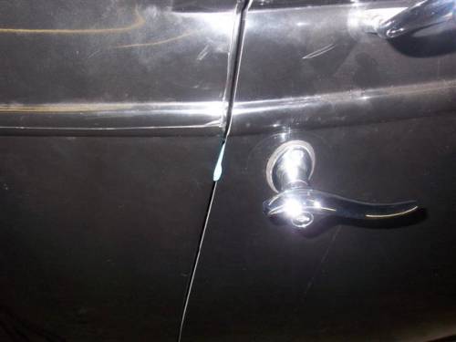
 In this picture, you’re also able to see the courtesy light I installed in the bottom of the door. At night, it will illuminate the ground as you’re getting out of the car. You never know what will be waiting in the hotel parking lot. |

Pete the glass guy installs four pieces of glass in the '32.

Well, the body is off and it's time to start welding up brackets and tabs that were just tacked in place this whole time.

In this article, I make a custom transmission dipstick mounting bracket off the back of the engine block.
This is another idea born from necessity… we hadn’t decided/bought a license plate frame or holder, so the idea began to be tossed around. On a roadster, plate positioning is a bit easier because the section below the trunk lid is taller; most plates get mounted there. But since there really isn’t enough height there on a 3 window, we decided to put it somewhere else. Here’s what we came up with.

Masking tape makes it easy to mark dimensions with a pen.

This is the little fixture I came up with to draw a line parallel with the tube. I have the spreader bar clamped to my bench, nestled up against a section of 1.5″ x 1.5″ tubing which is just hanging over the edge of the bench. I used a square and set the ruler so that the mark on the tube (which I made while the spreader bar was still on the car) was at an inch line. Doesn’t matter what number. I could then move the square along the tube and make marks at the number, then connect the dots. Voila! (That’s french for “eh!”)

Here’s a picture of my setup.

I used a cutoff disc to slot the spreader bar.

I cut the bottom off a Bob Drake stainless license plate frame…

…and tig welded it to the stainless spreader bar.

You can see where this is going…

I sectioned the piece that I cut off the bottom of the Bob Drake frame, and welded it to the spreader bar at the bottom of the license plate.

Now I have a short license plate that doesn’t interrupt any body lines. I still have to make a final decision on a light…

I made a brake pedal grommet from toolbox drawer liner and a spare washer.

This is another article from the ’32 build archive.
Odds and Ends / Powderific
Since the last “miscellaneous stuff” email, there hasn’t been a whole lot going on with the ’32, let alone much more miscellany. In highway terms, it’s “driving on the shoulder”. There are some items on the excuse sheet we’ve hung in the window, however.
First, the space we use to work on the car has been seized by hundreds of odds and ends, all with pallets as magic carpets. The people who were renting the building where we were storing this “stuff” moved, so we had to take it all out. It’s invaded our car building space; thus a chunk of the delay can be blamed away. Second, the powder coaters had some electrical issues while they were trying to set up their oven. The story is a bit longer than that, but all that’s important to me is I can’t be help responsible 🙂
In any case, we did get our powder coated parts and they look really great. We are doing most of the removable frame parts (bars, batwings, adjusters, brake pedal, etc.) in flat black. I have a thing for flat black. I would take a punch for flat black. So, with these parts in hand, I’m able to start reassembling the frame! Now if it wasn’t for all these odds and ends… I think I’m going to have an egarage sale. If you like, sign up for our newsletter and you’ll be able to see what edds and onds we’ve got and how cheap you can get them.

Now the next step is to make the frame black too so we can start putting the pieces together. I can’t believe the clarity of the parts even after the powder coating. The welds aren’t muddy looking, and the finish is very consistent. I hope it’s as durable as it is good looking. I’ll keep you posted on the frame painting process.

